
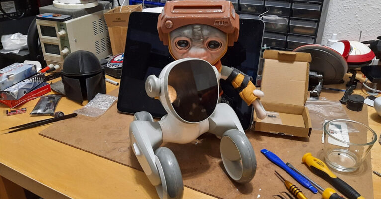

Today I (finally) found time to install Loona’s ear motors that arrived much later than KEYi Tech had advertised. The problem with that was that had they arrived earlier, I would have had the time to do this repair immediately. Because of the delivery delay I was only able to do it now.
I made a bunch of photos to show the process, especially since the video done by KEYi Technologies is missing some points and it looks way easier in that video to open the robot than it actually is.
I have a lab here, with lots of tools, multiple 3D printers, soldering station and some more stuff that makes things like the repair easier. “Normal” users will probably have more problems since they may not have tools handy if something does not go as planned or shown in the video.
My advise is to watch the complete video and then also reference this article as it is meant as an addition to that video, not to replace it.
I know that a lot of people will have already done this, but I wanted to show it anyway for those interested on how Loona looks on the inside.
So let’s start.
The first thing is: the tell you to drill a hole in the small cap that hides the one main screw that enables you to open the robot and to do that with the screwdriver they provided. Since the plastic is sturdy that would be a very tedious process, so I used my trusty Dremel to carefully drill a hole. I really would not want to do that with the screwdriver.

Removing the lower body part is quite easy after you unscrewed the screw behind that part. And now I know why I could not find any visible screws on Loona’s body. This is the one responsible for being able to get into the robot.
After that you have to remove four more screws. The two shown in the next images, and there are two more very similar below (not shown here).

In the official video you are now shown to use the blue plastic tool provided with the motors to press the upper body plastic part upwards. I tried that and I feared I would damage Loona in the process, because it would not come off and was warping alarmingly. I then used another screwdriver to help with unlocking the plastic noses holding the upper body part (on both sides of the body). Be very careful with this, you may damage the plastic if using a metal screwdriver like I did. Better to use something made out of plastic. I was careful, so no damage happened. But I think this is better than just trying to pull that body part upwards as shown in the video.

But at last I was able to remove the top cover and I was happy for being careful, because the wires going to the devices are very thin and fragile.
And I also noticed that the right wire was not in the connector. It may have slipped out while I tried to remove the top cover, but It may have been already out of the socket. That leads to a microphone in the body. I guess this is a microphone that tries to get body sounds of the robot that happen when driving and it is used to remove that body sounds from voice commands by subtracting the two audio signals. But that’s just an educated guess. If this was disconnected from the start it would explain why Loona almost never seemed to understand the wake word, but it worked if she stood still.
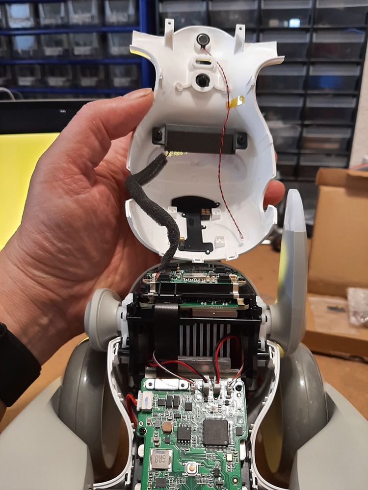
Here’s another image of the head and body boards.
 I then noticed a square rubber thingiemagook on my desk.

That seems to be a cover of one of the head microphones that fell off.
 To get to the ear motors you now have to remove some more screws from the lower body casing and from the face on both sides of the robot. See images.

The screws shown as “1” are the body screws. You also need to remove the two screws from the actual head motor shown as “2” (and two more, see further below).

And as written above, in the following pictures you see two more screws you need to remove to get the ear with motor out.

You should now unplug the ear motor plugs from the body board. Please note that they are installed at 180 degrees to each other. One red wire is in the back and one is in the front.

You can then carefully remove the ear motors.
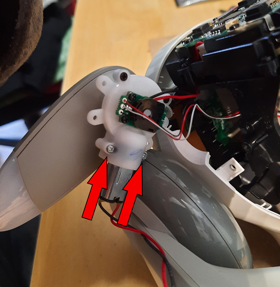
You have to loosen the two screws shown in the next image to pull out the motor of the ear unit. Do not unscrew them completely, just loosen them far enough so you are able to pull out the motor. That will need some rotating and bending of the motor but should be doable quite easy. If it is not, loosen the two screws a little more. You may want to use another small screwdriver for this as the screws are tight and the one provided by KEYi in the repair kit basically is a little too small for these screws. One with a tip that was a little bigger worked far better.
The next two images show the removed motor and the empty ear assembly without the motor.


You have to remove the conical cog from the top of the motor you just removed, because that will be put on the new motor. here is the top of the motor without that cogwheel.

On the outside the old (left) and the new motor (right) look identical, so let’s hope the new metal planetary gear is inside, or we will face the same problem again (but from what I understood, that is the case).

After putting the conical gear on top of the new motor you have to reinsert it into the ear assembly. This may need some rotating and turning. It is now smart to already put the motor cable into the correct path so you can reconnect it to it’s socket in the body board later. If you do not do this at this point it will become way more difficult doing this after reinstalling the ear motor assembly. The next picture shows where the cable has to go through.
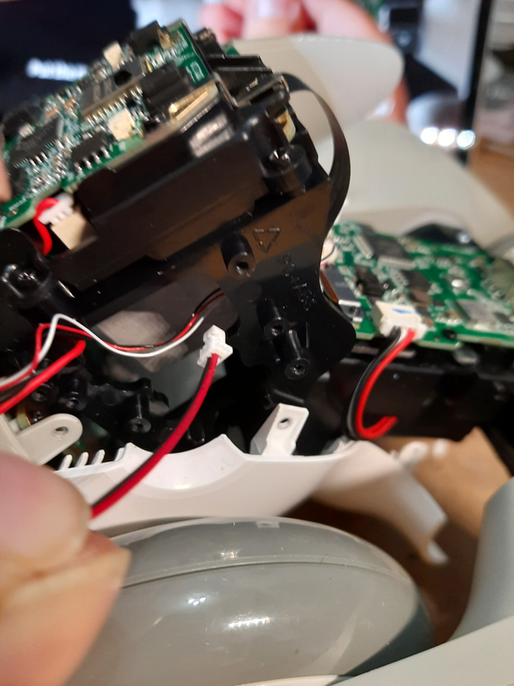
One of the ear assembly cables on the other side were way shorter than on the first side, which made it quite difficult to unscrew the both screws holding the motor without damaging the cable.

And after replacing that second motor that’s basically it, you now have to reverse the procedure and reassemble everything.
One small caveat: The plugs for the two cables leading to the top cover and that had to be unplugged at the beginning are very tiny. You may want to do this with pliers, especially if you have bigger fingers.

After reassembling everything I choose not to replace the screw cover with the new one provided in the repair kit, but use the one with the hole. This way I am able to open Loona in the future if the need arises or if I want to mod anything. since it is on thie underside and can hardly be seen the small hole is okay with me.

At the end of this article two more images of the head and the body board for reference (the head board is a little out of focus, sorry for that):

 To close this text:
From what I could see Loona’s build quality actually is quite amazing and you can absolutely say this is a quality product that was build and tooled quite well. Also the SMD soldering looked very good. Only negative points I had were that the plugs for the head cables are very tiny and it looks like they can drop out on their own by vibration and that some cables were unnesseccary short.
But aside from that it’s well worth the money and has very sound engineering.
Pingback: KEYi Tech: So this is what "improved communication" about Loona looks like? • thedroidyouarelookingfor
Please advise where I can buy the motors please.
Contact KEYiTech.
Pingback: Loona reapair service is one big mess • thedroidyouarelookingfor
How can two motors and where from plus I need a wheel motor as well my one has broke. I’ve got a secondhand but I love it a bit and I want to get it back as fully working. Can you please help?