


This has nothing to do with Vector, Emo or Eilik, but it definitely has to do with Droids. On Etsy you can buy multiple STL files by Droid Division to print and build droids based on Star Wars. One of them is the famous and instantly beloved Rat Catcher from THE BOOK OF BOBA FETT (and from CLONE WARS, it’s originally a “LEP service droid“).
In this article I tell those who bought the files for the Rat Catcher how to light the eyes and control that via a IR remote control over Arduino Nano (or another Arduino, the exact type really should not matter). But of course you can use this for other means of controlling things with a remote and an Arduino, the same principles apply.
This is no tutorial for complete Arduino or electronics newbies, you need a little prior experience with the boards, but there are myriads of articles and videos about that online which help to get you started.
You need:
- an Arduino Nano (or another Arduino)
- an IR receiver (more about this below)
- 20 3mm LEDs, color of your choice
- a breadboard for testing the setup
- some cables of different colors to connect everything
- Arduino IDE installed on your computer
 I will not cover connecting the Arduino to your computer or laptop or other Arduino basics, there are multitudes of tutorials on that and the exact way to do this depends on your setup and operating system. So you will need a basic familiarity on how to work with Arduinos.
Let’s start with setting up the IR receiver, we’ll add the LEDs later.
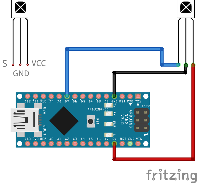
You need a IR receiver part. Most three-legged ones should work, you can see an example to the right, that’s the one I used in my setup and so I can confirm that it works. They have three connections: S, VCC and GND, GND being ground, VCC is power supply and S is for data. You can simply connect that to the Arduino to receive infrared signals from a remote control:
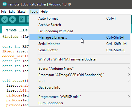
 Make sure you select the correct Arduino board in the IDE. To use the receiver you need to import the IRremote library into your Arduino IDE, so go to Menu->Tools-> Manage Libraries. There search for “IRremote” and install it (it is an older library and you may get “deprecated warnings when using it, but it will work fine and is more than enough for what we want to accomplish).

We have to find out what codes your IR remote sends so we can work with them depending on the button you press on the RC (caveat: most remote controls should work, but there may be exotic ones that will not. If nothing happens, try another remote). Enter the following into the Arduino IDE (you can just copy via the button in the top right corner of the code block & paste into the IDE):
#include <IRremote.h>

const int RECV_PIN = 7;
IRrecv irrecv(RECV_PIN);
decode_results results;

void setup(){
  Serial.begin(9600);
  irrecv.enableIRIn();
  irrecv.blink13(true);
}

void loop(){
  if (irrecv.decode(&results)){
        Serial.println(results.value, HEX);
        irrecv.resume();
  }
}
Now send this to the Arduino and open the serial monitor via Menu -> Tools -> Serial Monitor.

If you now press buttons on your remote you should see a LED on the Arduino blinking (confirming that this basically works) and codes listed in the serial monitor:
If you press short a single code will be generated. If you press longer, a single code will be generated, followed by multiple outputs that are something like “FFFFFFF”. Those are sent to report that the same buttons is kept pressed. These repeat codes are irrelevant for us, we only need the actual ones generated when a key is pressed.

Note down the keys and the codes generated by pressing them, we will need them later.
That was only a setup to find the codes that are generated by your remote control. We can now go to actually doing something with them. See the following setup:
 Make sure the polarity of the LEDs is correct. Usually the longer pins are the plus side. And need to be connected to the D-out pins 10, 11 and 12 of the Arduino. The shorter ends need each to be connected to a 1 KOhms resistor and those to ground. I show the setup with only three LEDs here, for the Rat Catcher eyes you should use three rows of three, four, three LEDs. You can of course test setup this on a breadboard.
Now copy the following code to the Arduino IDE
#include <IRremote.h>

const int RECV_PIN = 7;
IRrecv irrecv(RECV_PIN);
decode_results results;
const int led1pin = 10;
const int led2pin = 11;
const int led3pin = 12;

void setup(){
  irrecv.enableIRIn();
  irrecv.blink13(true);
  pinMode(led1pin, OUTPUT);
  pinMode(led2pin, OUTPUT);
  pinMode(led3pin, OUTPUT);
  digitalWrite(led1pin, LOW);
  digitalWrite(led2pin, LOW);
  digitalWrite(led3pin, LOW);
}

void loop(){
    if (irrecv.decode(&results)){

        Serial.println(results.value, HEX);

        switch(results.value){
          case 0x40BF00FF: //Keypad button "ON"
          digitalWrite(led1pin, HIGH);
          digitalWrite(led2pin, HIGH);
          digitalWrite(led3pin, HIGH);
          Serial.println("ON");
          }

        switch(results.value){
          case 0x40BF40BF: //Keypad button "OFF"
          digitalWrite(led1pin, LOW);
          digitalWrite(led2pin, LOW);
          digitalWrite(led3pin, LOW);
          Serial.println("OFF");
          }

        switch(results.value){
          case 0x40BF20DF: //Keypad button "1"
          digitalWrite(led1pin, HIGH);
          digitalWrite(led2pin, LOW);
          digitalWrite(led3pin, LOW);
          Serial.println("ON 1");
          }

        switch(results.value){
          case 0x40BFA05F: //Keypad button "2"
          digitalWrite(led1pin, HIGH);
          digitalWrite(led2pin, HIGH);
          digitalWrite(led3pin, LOW);
          Serial.println("ON 2");
          }
        irrecv.resume();
    }
}

//40BF00FF on
//40BF40BF off
//40BF20DF 1
//40BFA05F 2
Note that in the last lines I commented in the codes generated by the remote control buttons I wanted to use. Your codes will definitely vary. In the switch/case statements it is determined what code the IR Remote library reported pressed and according to that the LED pins are set to HIGH (powered and thus lit) or LOW (not powered, dark). Behind the “case” statements you will have to enter the codes you found for your keys, prefixed by a 0x (zero x).
Upload this to the Arduino and test it, it should work.
If you have questions, feel free to ask in the comments.
[Update:]
Here is an STL-file for a LED-holder that has ten 3mm holes for the LEDs and separators against light bleed.

Download the STL here: DDRCEyeLightSplitter_0003